ATS Products
*Image above is for illustration purpose only..
ATS-TEC15-46-032

Thermoelectric devices are semiconductor heat or refrigeration units which use the Peltier effect to create a heat flux between the two surfaces of the module. When a DC current is applied to the circuit, a thermoelectric module can work as a cooler or heater depending on the direction of current. A thermoelectric cooler (TEC), or solid state heat pump, transfers heat from one side of the device to the other side against the temperature gradient.

Product Details
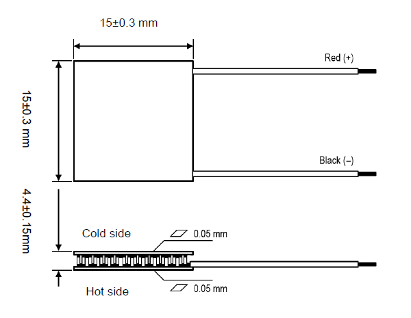
L=Length (mm);W=Width (mm); H=Height (mm);W (g)=Weight (g); Internal resistance (Ω)=Measured by AC 4-terminal method at 27°C; Imax=Maximum current at ΔTmax; Vmax=Maximum voltage at ΔTmax; Qmax=Maximum cooling capacity at Imax.,Vmax. and ΔT=0°C.; ΔTmax=Maximum temperature difference at Imax.,Vmax. and Qmax=0 W;
Features & Benefits
  • High efficiency, high performance
  • No sound or vibration
  • Compact structure, small in size, light in weight
  • Precise temperature control
  • Environmentally friendly
  • RoHS compliant
  • Exceptionally reliable

Applications

  • Medical instrumentation
  • Laser products
  • Lab science instrumentation
  • Clinical diagnostic systems
  • Photonics systems
  • Electronic enclosure cooling
  • Food & beverage cooling
  • Chillers (liquid cooling)
  • Temperature stabilizer
Thermal Performance
Schematic Image

*Image above is for illustration purpose only.
  1. Hot and Cold Sides Identification -If you want to know the TEC module’s hot side and cold sides, connect the red wire to the positive and the black wire to the negative polarity of the power supply. Turn the power supply on for 5 seconds (without the heat sink to dissipate the energy), carefully touch both sides of the modules, the hot and cold sides will be distinguished immediately. Longer than 5 seconds, without the heat sink, the TEC module may get damaged.
  2. Switching Hot and Cold SidesGenerally, the red and black wires symbolize positive and negative polarities, respectively. By connecting the red-wire to the positive and the black-wire to the negative polarity of the power supply, the hot and cold sides will turn on. By switching the polarity, red-wire to negative and black-wire to positive, the cold and hot sides will be switched. The applied DC power with the fluctuation coefficient should be less than 10%. Please note that when cooling and heating sides are exchanged, you should wait until the hot and cold sides get back to room temperature, (more than 15 minutes), otherwise, the TEC module may be damaged.
  3. Max Voltage and TC Number -How to determine the TEC’s maximum voltage and the number of thermocouples (TC)? The number of thermocouples is the number of crunodes between P and N types.
  4. Key Parameters -The value of ∆Tmax, Vmax, Imax and Qmaxare the limited value obtained according to the standard of SJ2855-2858 and SJ/T10135-10137-91. They are just for the selection purpose. In the practical application, the TEC voltage can be typically controlled within the general 12-13V DC. Please note, as the average working temperature increases, the current will decrease.
  5. Expected Life -To prolong the life of the TEC modules, they should be sealed. There are two ways to seal the TECs: one way is to use the 704-silica Gel, the other way is epoxy sealing. The aim of the sealing is to separate or isolate the modules from the outside air, thus the TEC can be protected from humidity and moisture to prolong expected life.
  6. Installation -
    a. clean both sides of the TEC,
    b. apply a layer of conductive silicon glue/grease or use any Thermal Interface Material (tape)
    c. apply the heatsinks
    d. TEC surface should be smooth and clean and in good thermal contact with heat source and the heat sink.
    e. To get a better cooling effect, you can use heat insulation materials to fill the space between the cold-plate and heat sink (the thickness is about 25-30mm).
  7. Functionality Testing -To see whether the TEC is functioning, the easiest method is measuring the resistance of the TEC. If you do not have the professional instrument, you can use bridge or ohmmeter to test the resistance. Please note that resistance tested by the multimeter is not exact, and it is a measure of electrical connectivity.
  8. Damage Prevention -TECs are delicate devices that can damage or crack as the result of a shock or falling from 10–20cm. Care should be given in handling, installing, and how introducing power when deploying a TEC in your application.
ATS-TEC15-46-032    (Data Sheet)
download data sheet
Complete Your Liquid Loop with ATS

ATS has the products needed to design a complete liquid cooling loop : iCDMs (Industrial Cooling Distribution Modules), Tubed and High Performance Cold Plates to transfer and remove the heat from the source; Heat Exchangers to transfer heat from the liquid to the air with or without a fan; Chillers to circulate and condition the fluid in the system, Compact Refrigeration Modules for very high capacity cooling. In addition , ATS offers Flow Meters to measure the volumetric flow rate of the fluid in the system and Leak Detectors to notify users of any leaks in the system.